2020年1月3日星期五

How to Tune Stepper Drivers

Turn power off, unplug the stepper motor cables, turn power back on and tune the stepper drivers.

When done, turn power off, plug in the stepper motor cables, turn power back on and test motor movement.

Don't tune digital stepper drivers with the motors plugged in, if you accidentally set current too high you can fry the motor or the stepper.

How to Tune Stepper Drivers


Don't plug or unplug stepper motors closed loop with the power on.

Measure DC voltage between the stepper trimpot and 12V ground. The ground at the 12V supply to the control board is fine to use.

Look up the correct current for your motor part number. If you have cheap Chinese motors with no part number, assume they have a max of 1.25A to be safe.

Look up the proper formula for your stepper drivers below, and find the voltage which corresponds with the current you want to set.

Pro tip: Get slip-on alligator clips for your multimeter. Clamp ground to a 12V ground wire and clamp positive to your screwdriver. This way you'll measure the voltage as you adjust and don't need three hands.

https://nema42motor.blogfree.net/?t=6111055
https://jaystep01.weebly.com/blog/gear-motor-basics-functions-and-design-process

2019年12月13日星期五

Something about Encoder resolution and accuracy

Stepper motor Encoders are at the heart of any closed loop servo system, providing feedback to the controller, which uses this information to determine if the motor reached the commanded position or velocity. Thus, encoder resolution and accuracy are essential to the proper operation of a closed-loop system.

Resolution is the distance over which a single encoder count takes place – it’s the smallest distance the encoder can measure. For rotary encoders, resolution is typically specified in terms of measuring units, or pulses, per revolution (PPR). Linear encoder resolution is most commonly specified as the distance over which the count takes place and is given in terms of microns (μm) or nanometers (nm). The resolution of an absolute encoder is specified in bits, since absolute encoders output binary “words” based on the encoder’s position.

Accuracy is the difference between the true position (or speed) of the device being measured and the position (or speed) reported by the encoder. For rotary encoders, it is specified in arcseconds or arcminutes, and for linear stepper motor encoders accuracy is typically given in microns.

Another term sometimes used in reference to encoder performance is “error.” Error is essentially the inverse of accuracy. In other words, accuracy specifies how close the encoder reading is to the true position, where error specifies how far the encoder is from the true position.

encoder resolution and accuracy
Factors that affect resolution
An encoder’s resolution is based on the number of lines (for an incremental encoder) or the pattern (for an absolute encoder) on the encoder disk or scale. Physically, resolution is fixed. Once an encoder is manufactured, there is no option to add more lines or patterns to the code disk.

Encoder Pulses Per Revolution


Factors that affect accuracy
While the number of lines or measuring units determines resolution, accuracy is affected by the width and spacing of these lines or units. Inconsistent width and/or spacing will cause errors in the timing of the pulses. For absolute encoders, accuracy is influenced by the precision with which the pattern is placed on the code disk.

encoders absolute incremental-

http://webautoshopper.com/cars/events/tops-on-choosing-a-stepper-motor-and-the-controller.html
http://bodybyhitch.com/shifouken43/blog/53/stepper-motor-controller-technology-overview

Most Effective Way to Commutate a BLDC DC Motor

Brushless DC motors
Brushless direct current electric motors, or BLDC motors for short, are electronically commutated motors powered by a DC electric source via an external motor controller. Unlike their brushed relatives, BLDC motors rely on external controllers to achieve commutation. Put simply, commutation is the process of switching the current in the motor phases to generate motion. Brushed motors have physical brushes to achieve this process twice per rotation, while BLDC motors do not, hence the name. Due to the nature of their design, they can have any number of pole pairs for commutation.


Motor commutation
Before delving too far into feedback options for BLDC motors, it is important to understand why they are necessary. BLDC motors come in single phase, 2-phase, and 3-phase configurations; the most common configuration being 3-phase. The number of phases matches the number of windings on the stator while the rotor poles can be any number of pairs depending on the application. Because the rotor of a BLDC motor is influenced by the revolving stator poles, the stator pole position must be tracked in order to effectively drive the 3 motor phases. Hence, a motor controller is used to generate a 6-step commutation pattern on the 3 motor phases. These 6-steps, or commutation phases, move an electromagnetic field which causes the permanent magnets of the rotor to move the motor shaft.


Position feedback
Since the inception of the brushless dc motor, Hall-effect sensors have been the workhorse for commutation feedback. For 3-phase control, only three sensors are required, and with a very low per-unit cost, they are easily the most economical option to achieve commutation from a pure BOM cost perspective. Hall sensors are embedded into the stator of the motor to detect rotor positon, which is used to switch the transistors in the 3-phase bridge to drive the motor. The three Hall-effect sensor outputs are commonly noted as the U, V, and W channels. While Hall sensors are an effective solution for commutating BLDC motors, they only address half the needs of a BLDC system.

How to Use BLDC Hall Sensors as Position Encoders
How to Use Hall Effect To Drive Brushless DC Motor


2019年11月27日星期三

NEMA 42 Stepper Motor Applications in CNC AND Robotics Industry

NEMA 42 stepper motor is the largest stepper motor of the stepper motor family. This is known to be the finest type of stepper motor. It has the unique features of both, permanent and variable reluctance motor. It is an electronically driven motor, and it is used in the robotics industry and many other industries. The stepper motor is mainly used in the applications where precise and efficient motion control is required whether the motion is linear or rotational. In case of rotational motion, when it receives digital pulses in an accurate sequence it allows the shaft of the stepper motor to rotate in discrete step increments.
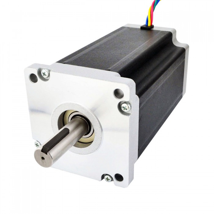
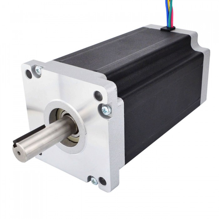
Dual Shaft Nema 42 CNC Stepper Motor 30Nm (4248oz.in) 8A 110x201mm 4 Wires
Robotics Industry:

NEMA 42 stepper motor is widely used in the field of robotics as it provides high torque and has the quality to work for precise control. Nowadays as the world is getting dependable on the technology robotics industry has got a great chance to grow. The growing field of robotics is partially dependable of NEMA 42 stepper motor for their growth, as it is the best electrical motor to be used for the robotics applications.
Nema Size 42 CNC Stepper Motor Bipolar 30Nm (4248oz.in) 8A 110x201mm 4 Wires

CNC Industries:

CNC (Computer Numeric Control) industries are those who manufactures CNC equipment like CNC routers, CNC milling machine, and various other CNC products. These equipment are computer controlled devices that are used for cutting applications. These applications also require precise control and hence NEMA 42 Stepper motor is highly preferred electrical motors for CNC applications.

3-D Printing or Rapid Prototyping Industries:

3-D printers requires precise control and accuracy for their operation and hence these type of printers use NEMA 42 Stepper motors. These motor provide a high level of precision because of the direct relationship between the rotation angle and the input pulse. They can be paused, and the direction of rotation can be reversed with a great precision, making the NEMA 42 Stepper motor an excellent component to be used for rapid prototyping applications.

2018年9月21日星期五

High performance microstep driver for unipolar stepper motors


What is it? 

I originally designed the LiniStepper as a versatile PCB that could be used to drive most small to medium UNIPOLAR stepper motors for my own CNC projects. Because this was designed for me the design may seem a little eccentric. There is massive reliability from over-rating components, great versatility from using discrete power components and a PCB with numerous setup options, and an on-board microprocessor that can be programmed to do any microstepping mode and even act as complete motion controller "brain" all on the one board if needed.

Since "proper" commercial stepper motor drivers for sale are very expensive there was an interest from people to buy the LiniStepper as a low cost kit that will provide good performance for home CNC uses. The LiniStepper soon evolved into an open-source project with the help of the wonderful people who run the PICLIST electronics forum.

The LiniStepper gives great motor performance with some very nice microstepping features, but it is linear in its method of controlling motor current, so it can give off a lot of heat if driving a large motor. In most cases this is no big deal, you just bolt it to a decent heatsink and maybe a small PC type fan and enjoy the great performance of smooth linear current control.


Features:
Step modes of 200, 400, 1200, 3600 steps/rev
(full step, half step, 6th step, 18th step)
Linear current smoothing, gives smooth "stepless" operation
Extremely rugged
Uses large power transistors, not a flimsy stepper driver chip
Best suited for stepper motors up to 1.5A per phase
Can be used for 4A per phase BUT ONLY IN FULL STEP MODE
PSU voltage 4v to 35v
Can be set up for a huge range of motor sizes
On-board PIC chip and free source code
PIC chip is ALREADY programmed for you!
Source code can be modded to give ANY step resolution or infinite angle control
Requires +5v logic supply for PIC
Has "standard" step and direction inputs
Compatible with most freeware home CNC driver software
Can be wired directly to a PC parallel port for home CNC
Works with 5-wire and 6-wire (unipolar) motors

Disadvantages;
It gets hot with larger motors, needs a big heatsink
It is a kit, you have to build it
Does NOT work with 4-wire (bipolar) motors


High performance 

The Linistepper is a bit like myself; eccentric, quirky, rugged, old-fashioned and offers a very high level of performance. :o)

As far as I know this is the only LINEAR constant-current microstepping stepper driver available for sale apart from a couple of very expensive high-end industrial units costing many hundreds of $.


Look at that linear smoothing! This is the actual current through one motor winding in 3600 step mode, measured through one of the current sense resistors.


Open-source project 
This one page is all I have here on the LiniStepper, but there is a large open-source project available which contains many pages;
Technical, how it works and linear microstepping theory
How to build it with step by step photos
Circuit diagram and parts list
PCB parts layout
High torque half-stepping theory
Full PIC .asm software
Tips for using it
How to tune it for different step motor sizes
Owner's questions and answers

You can buy the kit there too and it has been priced cheaply, for a similar price to the costs of the parts alone if bought from Digikey or other hobby electronics stores. The kit includes all the components, a high quality plated through hole double sided PCB, the plugs/sockets for all connections, and mounting hardware for the power transistors but DOES NOT include heatsink angle bracket or heatsink. All kit instructions are web-based and can be downloaded. The (very small!) profits from kit sales are divided equally between myself and the forum and help to support the forum.

hybrid Stepping Motor Advantages and Disadvantages

2018年9月20日星期四

HOW TO CONTRO L LINEAR STEPPER MOTOR ACTUATORS

n this post we will be going over how to use relay boards to control the motion of linear actuators. We have 2-channel, 4-channel and 8-channel relay boards available and each one does the same thing, the only difference being how many channels are usable. We will be combining the relay boards with our LC-066 Arduino Uno to show off their control capabilities. The relays control the direction in which the actuator moves. They work by using current from the input source to activate an electromagnet, which pulls a switch that allows higher currents on the opposite side of the relay to flow.
IMG_0050

On the control side of our relays you will find a GND pin, IN pins numbered from 1 to 8 depending on the relay model, and a VCC pin. Our relays require a fair amount of power to stay activated so we'll need at least a stable 5V power supply. Otherwise the Arduino will have trouble powering the higher channel relay modules. Usually they can produce a few hundred milliamps which is more then enough to power a 2 channel relay module like our LC-200 but no where near enough for an 8 channel relay module like our LC-202. For this example we'll be using the 2 channel relay. As for wiring the relay modules you'll need to follow some simple steps.
On the control side of the relay, first we need to connect our 5V power supply to the VCC and GND pins. Next we'll need to connect the IN pin to the corresponding Arduino pin, then the relays will activate once the IN pins are connected to the GND pins. On the relay side there are three main parts of each relay, three screw terminals.
IMG_0041

These terminals are referred to as the Normally Closed (NC) connection, the top one, the Common (COM) connection, the middle one, and the Normally Open (NO) connection on the bottom. If there are no connections to the IN pin then the relay will connect between the NC and COM terminals. If the 5V power source is connected to the IN pin then the relay will connect between the NC and COM terminals as well. Finally if you connect the IN pin to the GND pin the relay will connect between the NO and COM terminals.

IMG_0044

Now that everything is wired up its time for some basic coding with the Arduino Uno. Below is an example showing how the programming works.
const int forwards = 7;
const int backwards = 6;//assign relay INx pin to arduino pin

void setup() {
 
pinMode(forwards, OUTPUT);//set relay as an output
pinMode(backwards, OUTPUT);//set relay as an output

}

void loop() {
  
 digitalWrite(forwards, LOW);
 digitalWrite(backwards, HIGH);//Activate the relay one direction, they must be different to move the motor
 delay(2000); // wait 2 seconds

 digitalWrite(forwards, HIGH);
 digitalWrite(backwards, HIGH);//Deactivate both relays to brake the motor
 delay(2000);// wait 2 seconds
 
 digitalWrite(forwards, HIGH);
 digitalWrite(backwards, LOW);//Activate the relay the other direction, they must be different to move the motor
 delay(2000);// wait 2 seconds

 digitalWrite(forwards, HIGH);
 digitalWrite(backwards, HIGH);//Deactivate both relays to brake the motor
 delay(2000);// wait 2 seconds

}


We've included a video showing off what we talked about in this article, be sure to check it out and stay tuned for more videos like it in the coming weeks. In conclusion, using relays to control linear actuators allows for some creative control options like the one we went over above and combining them with other motion control devices provides even more capabilities. If you want to learn more about our linear step motor actuators and motion control devices check out our blog for a variety of different articles like this. You can also contact us and talk to one of our on staff expert engineers to answer some of your more specific questions.

See more:https://www.oyostepper.com/